The transformation of manufacturing through automated pick-and-place systems represents one of the most significant technological advances in modern production environments. From humble beginnings in manual assembly lines to today’s sophisticated AI-driven platforms, these systems have revolutionised how manufacturers approach speed, precision, and scalability. Contemporary pick-and-place technology achieves placement rates exceeding 150,000 components per hour with positional accuracy measured in micrometers, fundamentally changing the economics of high-volume manufacturing.
This technological evolution spans decades of incremental improvements and breakthrough innovations, each building upon previous achievements to create increasingly capable systems. The journey from mechanical positioning devices to intelligent vision-guided robots illustrates how manufacturing automation continues to push the boundaries of what’s possible in production efficiency and quality control.
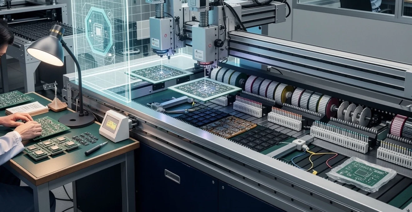
Historical development of Pick-and-Place technology from manual assembly to automated systems
The origins of pick-and-place technology can be traced back to the growing complexity of electronic manufacturing in the 1960s and early 1970s. As circuit boards became more densely populated and component sizes continued to shrink, manufacturers recognised that human operators could no longer maintain the speed and accuracy required for competitive production. The semiconductor industry’s rapid growth created an urgent need for automated solutions that could handle thousands of tiny components with consistent precision.
Early automation efforts focused on replacing the most repetitive aspects of manual assembly, where operators would spend hours placing identical components using tweezers and magnifying equipment. These initial systems, though primitive by today’s standards, demonstrated the potential for significant productivity improvements whilst reducing the physical strain on workers. The economic benefits became immediately apparent as manufacturers could operate continuously without fatigue-related errors or productivity drops.
Transition from Hand-Placement techniques to mechanical insertion systems in the 1970s
The 1970s marked a pivotal decade in manufacturing automation, witnessing the emergence of the first mechanical insertion systems designed to replace manual component placement. These early machines utilised pneumatic actuators and simple positioning mechanisms to pick components from magazines or reels and place them onto pre-drilled circuit boards. The mechanical precision achieved by these systems, whilst modest compared to modern standards, represented a quantum leap from hand-placement techniques.
Manufacturers like Universal Instruments and Dynapert pioneered the development of axial insertion machines that could handle through-hole components with reasonable accuracy. These systems typically achieved placement speeds of 3,000 to 5,000 components per hour, dramatically outpacing manual assembly whilst maintaining consistent quality. The introduction of component feeders and automated board handling further enhanced productivity, creating the foundation for modern high-speed manufacturing lines.
Introduction of Computer-Controlled positioning with fuji CP-40 and universal instruments GSM systems
The integration of computer control systems in the 1980s transformed pick-and-place technology from mechanical automation into intelligent manufacturing platforms. Fuji’s CP-40 system introduced sophisticated servo motor control and programmable positioning algorithms that could adapt to different component types and board layouts. This flexibility marked a departure from fixed automation towards reconfigurable systems that could handle multiple product variants without extensive retooling.
Universal Instruments’ GSM (Genesis Series Machine) platform further advanced computer-controlled positioning by introducing multi-head gantry systems capable of simultaneous component placement. These systems featured advanced interpolation algorithms that optimised placement sequences to minimise cycle times whilst maintaining positional accuracy within ±0.05mm. The ability to programme complex placement patterns and automatically adjust for component variations significantly reduced setup times and increased overall equipment effectiveness.
Surface mount technology integration with Fine-Pitch component handling capabilities
The widespread adoption of surface mount technology (SMT) in the 1990s created new challenges for pick-and-place systems, requiring unprecedented precision for handling components with lead pitches as fine as 0.4mm. Traditional through-hole insertion techniques proved inadequate for these miniaturised components, necessitating entirely new approaches to component handling and placement verification. Surface mount integration demanded sub-micron positioning accuracy and sophisticated vision systems for component alignment.
Advanced nozzle technologies emerged to address the unique requirements of SMT component handling, including specialised tips for different package types and vacuum systems optimised for small component retention. Placement forces became critical parameters, as excessive force could damage del
icate terminations or crack solder joints before reflow. To address this, manufacturers introduced closed-loop force control and z-axis compliance mechanisms, allowing the placement head to “float” slightly as it contacted the board. Combined with fiducial recognition and on-the-fly vision alignment, these innovations enabled reliable fine-pitch component placement at speeds that would have been unimaginable in the early days of manual assembly.
As component sizes shrank further to 0402, 0201, and now 01005 packages, pick-and-place systems evolved to deliver ever tighter tolerances. Machine builders refined gantry stiffness, reduced head mass, and improved ball screw and linear motor technologies to maintain accuracy at high speeds. The result was a new generation of high-speed pick-and-place machines capable of handling both tiny passives and complex integrated circuits on the same platform, supporting flexible, high-mix production without sacrificing throughput.
Multi-head gantry systems development by panasonic and JUKI corporation
The pursuit of higher throughput drove the development of multi-head gantry systems in the late 1990s and early 2000s. Panasonic and JUKI Corporation were among the leaders in introducing architectures where multiple placement heads operated in parallel on a shared gantry or dual-gantry configuration. By distributing placement tasks intelligently across several heads, these systems dramatically increased components per hour without compromising placement quality.
Panasonic’s high-speed platforms, for example, combined dedicated high-speed chip shooters with more flexible placement heads capable of handling odd-form or fine-pitch devices. JUKI’s modular systems took a similar approach, allowing manufacturers to configure machines with different head types depending on product mix and volume requirements. This modularity helped electronics manufacturers scale capacity incrementally, adding extra heads or modules as demand grew rather than investing in entirely new lines.
Multi-head gantry designs also enabled advanced optimisation strategies such as head balancing and dynamic task allocation. Machine software could analyse a production schedule, assign components to the most suitable head, and minimise non-productive travel by grouping placements logically. For high-speed manufacturing, this meant not just faster pick-and-place operations, but smarter utilisation of every axis movement, squeezing maximum productivity out of each production shift.
Advanced vision system integration and component recognition technologies
As mechanical capabilities matured, the bottleneck in high-speed pick-and-place systems shifted from motion control to perception and decision-making. It was no longer enough to move quickly; machines needed to “see” and understand components in real time. Advanced vision system integration became a defining characteristic of modern pick-and-place technology, enabling reliable placement even when dealing with miniature components, variable packaging, and warped substrates.
Today, high-speed manufacturing platforms routinely integrate multiple camera systems, 3D sensors, and sophisticated illumination setups to support component recognition and PCB inspection. These vision systems not only verify that the right component is being placed in the right location, but also detect subtle variations that could lead to quality issues later. In effect, vision technology has turned the pick-and-place machine into both a placement tool and an inline inspection station.
Machine learning algorithms for real-time component classification and orientation detection
The latest generation of pick-and-place systems leverages machine learning algorithms to enhance component recognition and orientation detection. Rather than relying solely on fixed templates or predefined geometric features, these systems train models on large datasets of component images, allowing them to recognise new package variants and slight manufacturing tolerances more robustly. For high-mix, low-volume environments in particular, this reduces the time spent teaching each new part number.
Real-time component classification is especially valuable when feeder errors or supply chain variations introduce unexpected changes, such as alternative supplier components or revised markings. Machine learning models can adapt to these differences while maintaining the accuracy required for high-speed placement. You can think of this as giving the machine a “visual intuition” similar to an experienced operator who can recognise parts at a glance, but with the consistency and speed of automation.
Orientation detection has also benefited from AI-based approaches. Instead of relying on simple edge detection, modern algorithms evaluate complex visual cues such as lead patterns, polarity markings, and subtle asymmetries in the package. This allows pick-and-place systems to correct mis-rotated components on the fly, reducing scrap and rework. For manufacturers facing constant component changes, AI-driven vision significantly lowers engineering overhead and speeds up new product introduction.
High-resolution camera systems with sub-pixel accuracy for 0201 component placement
The move towards 0201 and 01005 chip components demanded a step change in vision resolution and precision. To place components that are often less than 0.5 mm in length, pick-and-place machines now employ high-resolution camera systems with sub-pixel accuracy. By interpolating between individual sensor pixels, these systems can determine component positions and orientations to a fraction of a pixel, supporting placement accuracies of a few micrometres.
Sub-pixel accuracy is achieved through advanced image processing techniques, including centroid calculations, edge fitting, and pattern-matching algorithms optimised for speed. High frame-rate cameras, often combined with strobe or structured illumination, capture sharp images even as the placement head moves rapidly across the board. The result is a high-speed manufacturing process where vision inspection does not become a throughput bottleneck.
For you as a manufacturer, this level of precision translates into higher yields, particularly on densely populated boards where even minor misalignment can cause solder bridging or open circuits. Moreover, the same cameras that guide placement can also perform inline quality checks, such as verifying solder paste deposits or inspecting previously placed components. This dual use of vision improves overall process control without adding extra equipment.
Optical character recognition implementation for IC package verification
As integrated circuits become more complex and similar in appearance, the risk of misplacing or misidentifying IC packages increases. To mitigate this, many modern pick-and-place systems incorporate optical character recognition (OCR) to read markings directly from component packages. OCR allows the machine to verify that the component loaded in a feeder matches the bill of materials before it is placed on the board.
Implementing OCR in a high-speed pick-and-place environment presents unique challenges. Markings can be small, low contrast, or partially obscured by reflections, and the system must read them without significantly slowing down the line. Machine builders address this with specialised lighting, angled cameras, and optimised OCR algorithms tuned for typical semiconductor fonts and codes. Once configured, OCR becomes a powerful safeguard against costly field failures caused by incorrect IC placement.
Beyond basic verification, OCR data can be logged and linked to production traceability systems, supporting regulatory compliance and customer requirements for end-to-end visibility. When a board fails test or a recall is necessary, you can trace back exactly which lot of components was used, which machine placed them, and at what time. In industries such as automotive or medical electronics, this detailed traceability is no longer optional—it is a core part of risk management.
3D vision systems for warped PCB compensation and height measurement
Traditional 2D vision is sufficient when boards are perfectly flat, but real-world PCBs often exhibit warpage due to material stresses, high-temperature processes, or uneven component loading. 3D vision systems have emerged as an effective solution, enabling pick-and-place machines to measure board topography in real time and adjust placement heights accordingly. By mapping the z-height across the entire panel, the machine can maintain optimal standoff and contact forces for each component.
Several 3D sensing approaches are used in high-speed manufacturing, including laser triangulation, structured light projection, and time-of-flight sensors. These technologies generate dense height maps that inform not only placement height but also coplanarity checks and solder paste volume assessments. In essence, the machine gains a three-dimensional understanding of the workpiece, improving robustness against mechanical variations.
For advanced packaging and high-density interconnect designs, 3D height measurement is critical to ensure reliable solder joints and to avoid component damage. When you’re placing fine-pitch BGAs or flip-chips, a few tens of micrometres in height error can mean the difference between a robust interconnect and a latent defect. 3D vision systems provide the feedback needed to keep the process within these tight tolerances, even as boards become thinner and more complex.
High-speed servo motor control and precision mechanical engineering
Behind every high-speed pick-and-place system is a carefully engineered combination of servo motor control and precision mechanics. The ability to place tens of thousands of components per hour with micrometre-level accuracy depends on more than just fast motors; it requires coordinated motion control, rigid structures, and advanced feedback systems. Think of it as a high-performance race car: raw engine power only delivers results when matched with a well-tuned chassis, suspension, and braking system.
Modern pick-and-place machines rely heavily on linear motors and direct-drive rotary axes to reduce backlash and mechanical hysteresis. High-resolution encoders, often with resolutions down to sub-micrometre levels, provide continuous feedback to the motion controller, which calculates precise trajectories for each axis. Advanced servo algorithms manage jerk, acceleration, and deceleration profiles, ensuring that the placement head moves smoothly without exciting resonances that could degrade accuracy.
Mechanical engineering plays an equally important role. Lightweight yet stiff gantries, carefully balanced placement heads, and optimised belt or linear guide designs minimise vibration and flex during rapid movements. Engineers use finite element analysis and modal testing to identify and dampen potential resonance frequencies. The result is a motion platform that can accelerate at several g while maintaining repeatability, supporting the high-speed manufacturing targets demanded by modern electronics production.
From a practical standpoint, this engineering sophistication gives you more process window to work with. You can run faster without sacrificing first-pass yield, and you can support a wider range of component sizes and board designs on the same equipment. In highly competitive markets, the combination of speed and flexibility enabled by advanced servo control often becomes a key differentiator between manufacturers.
Industry 4.0 integration with IoT connectivity and predictive maintenance systems
The evolution of pick-and-place systems has not occurred in isolation; it is deeply intertwined with the broader shift towards Industry 4.0 and connected manufacturing. Today’s high-speed pick-and-place platforms function as intelligent nodes within a larger digital ecosystem, exchanging data with MES, ERP, and quality management systems in real time. This connectivity allows you to manage production lines with unprecedented visibility and control.
IoT-enabled sensors embedded throughout the machine continuously monitor parameters such as motor currents, vibration levels, feeder performance, and head utilisation. This data is streamed to analytics platforms that can identify patterns, correlate events, and flag emerging issues before they impact throughput. For example, a slight increase in axis vibration might indicate bearing wear, prompting a maintenance intervention during a scheduled downtime instead of causing an unexpected stoppage.
Predictive maintenance has become a cornerstone of high-speed manufacturing, reducing unplanned downtime and extending equipment life. Rather than relying on fixed service intervals, you can base maintenance decisions on actual usage and condition data. Over time, machine learning models refine their predictions, offering increasingly accurate estimates of remaining useful life for critical components. This data-driven approach aligns perfectly with lean manufacturing principles, as it helps you eliminate waste associated with both over-maintenance and unexpected failures.
Industry 4.0 integration also supports advanced production strategies such as lot-size-one manufacturing and rapid product changeovers. By linking the pick-and-place system directly to digital work instructions and product recipes, changeovers can be executed with minimal manual intervention. Feeder setups, placement programs, and inspection criteria are automatically loaded based on the digital order, enabling you to respond quickly to customer demand without sacrificing consistency or traceability.
Component handling innovations for advanced packaging technologies
As semiconductor and electronics packaging technologies have evolved, pick-and-place systems have had to keep pace with increasingly complex component formats. Advanced packaging approaches such as ball grid arrays (BGAs), chip scale packages (CSPs), flip-chips, and fine-pitch connectors pose unique handling challenges. Addressing these requires a combination of specialised nozzles, refined placement algorithms, and tightly controlled environmental conditions within the high-speed pick-and-place process.
In many ways, the evolution of component handling mirrors the broader trajectory of the industry: from relatively simple, robust packages to ultra-miniaturised, high-density interconnect solutions. Each new packaging generation pushes pick-and-place technology to deliver better coplanarity control, finer placement accuracy, and gentler handling. For manufacturers aiming to stay at the cutting edge, understanding these innovations is essential to designing future-proof production lines.
Ball grid array and chip scale package placement techniques
Ball grid array and chip scale packages introduced a fundamental change in how interconnects are formed, replacing visible leads with arrays of solder balls hidden beneath the package. This makes precise placement and solder joint formation more critical, as misalignment is not easily detected visually before reflow. High-speed pick-and-place machines have adapted by using vision systems to locate package edges, fiducial marks, or even the solder ball pattern itself to ensure accurate alignment.
BGA and CSP placement techniques often incorporate specialised vacuum nozzles designed to distribute suction evenly across the package surface, preventing warping or damage during handling. Z-axis control becomes particularly important: the placement head must contact the solder balls with just enough force to seat the package into the paste without deforming the balls or smearing the paste. Closed-loop force feedback and programmable placement heights are therefore standard features on modern high-speed pick-and-place platforms handling these devices.
Post-placement, many lines integrate automatic optical inspection (AOI) or X-ray inspection to verify BGA and CSP solder joints, but the foundation of a reliable process is still accurate placement. By combining precise mechanics, advanced vision, and tailored nozzles, contemporary pick-and-place systems routinely achieve BGA placement yields that would have been considered exceptional only a decade ago. For you, this reliability translates into fewer rework operations and greater confidence in field performance.
Flip-chip bonding integration with thermal compression and underfill processes
Flip-chip bonding takes the concept of hidden interconnects a step further, mounting bare die directly to the substrate with solder bumps or copper pillars. This advanced packaging technology offers excellent electrical and thermal performance but places extreme demands on placement accuracy and process integration. In high-speed manufacturing, flip-chip placement must often be coordinated with thermal compression, flux or solder paste application, and subsequent underfill processes.
To support flip-chip assembly, pick-and-place machines are equipped with die-handling capabilities, including ultra-clean vacuum paths, anti-static measures, and delicate collet designs. Vision systems typically inspect both the die and the substrate, aligning bumps to pads with micrometre precision. During thermal compression, controlled temperature and force profiles ensure proper bump collapse and intermetallic formation, with the pick-and-place equipment often synchronised to the bonding system through tight process control loops.
Underfill application, which reinforces the mechanical connection and improves thermal cycling performance, must occur after placement and bonding but before final curing. Integrating these steps into a cohesive, high-speed process requires close cooperation between equipment vendors and process engineers. When executed correctly, however, flip-chip integration allows you to build compact, high-performance modules that meet the demands of 5G, high-speed computing, and advanced automotive applications.
Fine-pitch connector assembly for high-density interconnect applications
Fine-pitch connectors, such as board-to-board mezzanine connectors and high-speed backplane interfaces, are another area where pick-and-place technology has had to adapt. These connectors often feature pin pitches of 0.4 mm or less and require precise coplanarity and alignment to ensure reliable mating. Misplacement by even a small margin can lead to intermittent connections, signal integrity issues, or mechanical interference during assembly.
High-speed pick-and-place systems handle fine-pitch connectors using dedicated grippers or customised nozzles that engage robust areas of the connector body without deforming delicate contacts. Vision alignment typically relies on recognising castellations, locating pins, or moulded reference features on the connector housing. In some cases, 3D vision is used to confirm that the connector sits flat on the board prior to soldering, preventing tilt that might compromise mating height.
Because many high-density interconnect applications involve multiple stacked or opposing connectors, consistent placement is vital to ensure that all mating pairs align correctly in the final assembly. For you as a designer or process engineer, this means collaborating closely with connector suppliers and machine vendors to define acceptable tolerances and to validate the assembly process. When fine-pitch connector assembly is optimised, you gain the freedom to design compact, high-bandwidth systems without sacrificing manufacturability.
Performance benchmarking and throughput optimisation strategies
With so many variables influencing pick-and-place performance—component mix, board design, feeder configuration, and motion characteristics—benchmarking and optimisation become essential. High-speed manufacturing environments increasingly rely on detailed performance metrics to understand where time is being lost and how throughput can be improved without compromising quality. Rather than focusing solely on headline placement rates, savvy manufacturers look at effective components per hour, overall equipment effectiveness (OEE), and real-world cycle times across product families.
Performance benchmarking typically starts with a clear baseline: measuring current placement rates, changeover times, feeder setup durations, and downtime causes. Machine software and factory analytics tools then break these figures down into actionable insights. For example, you might discover that a particular feeder bank is responsible for a disproportionate number of line stops, or that non-optimised placement sequences are causing excessive head travel. Armed with this data, you can implement targeted improvements that yield significant gains.
Throughput optimisation strategies often revolve around three core levers: program optimisation, hardware configuration, and process standardisation. Program optimisation involves using software tools to reorder placements, balance workloads across multiple heads or machines, and minimise non-productive movements. Hardware configuration focuses on choosing the right combination of feeders, nozzles, and head types for your product mix, avoiding unnecessary head changes or feeder swaps.
Process standardisation might be the most underrated lever. By harmonising component libraries, feeder assignments, and panel designs across products, you reduce the amount of reconfiguration needed between jobs. This is particularly powerful when combined with quick-change feeder carts and offline setup stations, allowing you to prepare the next job while the current one is still running. In a high-speed manufacturing environment, shaving even a few minutes off each changeover can translate into hours of extra productive time each week.
Ultimately, the evolution of pick-and-place systems is not just a story of faster machines and more advanced technology. It is about how you, as a manufacturer, harness these capabilities to build a more flexible, resilient, and efficient production operation. By understanding the historical context, embracing modern vision and motion control, and exploiting Industry 4.0 connectivity, you can position your high-speed manufacturing lines to meet both today’s demands and tomorrow’s challenges.