The relentless miniaturisation of electronic devices has created unprecedented thermal challenges that traditional printed circuit board materials simply cannot address. When components generate substantial heat within confined spaces, the choice of substrate material becomes critical for preventing catastrophic failure and ensuring long-term reliability. Aluminium printed circuit boards (PCBs) have emerged as the gold standard for applications where thermal management is paramount, offering superior heat dissipation capabilities that far exceed conventional FR-4 materials.
The physics of heat transfer in electronic assemblies demands careful consideration of thermal pathways from heat-generating components to ambient air. Standard organic substrates act as thermal insulators, trapping heat near sensitive junctions and creating localised hot spots that accelerate component degradation. Aluminium PCBs fundamentally alter this thermal landscape by incorporating a metal core that serves as an efficient heat conductor, rapidly transferring thermal energy away from critical components.
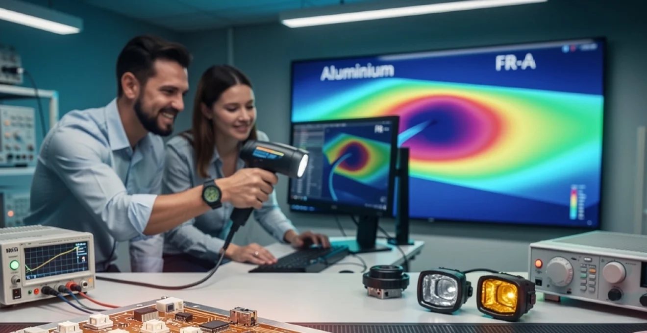
Thermal conductivity properties of aluminium PCB substrates
The thermal performance of aluminium PCBs stems from their unique multilayer construction, which combines the electrical properties of traditional circuit boards with the thermal advantages of metal substrates. The typical structure consists of a copper circuit layer, a thermally conductive dielectric material, and an aluminium base plate. This configuration enables thermal conductivities ranging from 1.0 to 8.0 W/m·K, compared to the modest 0.3 W/m·K offered by standard FR-4 materials.
Understanding thermal resistance becomes crucial when evaluating aluminium PCB performance. The total thermal resistance from component junction to ambient comprises several elements: junction-to-case, interface materials, dielectric layer, and aluminium base to heatsink. Minimising each of these thermal barriers requires careful material selection and design optimisation to achieve the lowest possible junction temperatures during operation.
Comparative analysis: aluminium vs FR-4 thermal performance metrics
Quantitative analysis reveals the dramatic thermal performance differences between aluminium and FR-4 substrates. In high-power LED applications, aluminium PCBs can reduce junction temperatures by 30-60°C compared to equivalent FR-4 designs. This temperature reduction directly translates to improved reliability, with component lifespans potentially doubling or tripling due to reduced thermal stress.
| Property | Aluminium PCB | FR-4 PCB |
|---|---|---|
| Thermal Conductivity (W/m·K) | 1.0 – 8.0 | 0.3 |
| Thermal Resistance (°C/W) | 0.5 – 2.0 | 15 – 25 |
| Maximum Operating Temperature (°C) | 150 – 200 | 130 |
| CTE (ppm/°C) | 23 | 14 – 17 |
Metal core PCB thermal interface materials and heat dissipation coefficients
The dielectric layer serves as the critical thermal interface between the copper circuitry and aluminium base, requiring materials that balance electrical isolation with thermal conduction. Modern thermal interface materials (TIMs) utilise ceramic fillers such as aluminium oxide, boron nitride, or aluminium nitride to achieve thermal conductivities exceeding 2.0 W/m·K while maintaining electrical breakdown voltages above 3000V.
Berquia-oxide filled polymers represent the most common dielectric material, offering excellent thermal performance at moderate cost. However, applications demanding maximum thermal efficiency may justify the higher expense of boron nitride or aluminium nitride filled systems, which can achieve thermal conductivities approaching 8.0 W/m·K. The selection process must consider not only thermal
performance of the dielectric itself, but also its bond strength, long-term stability under thermal cycling, and compatibility with the chosen aluminium alloy. In practice, you are often trading off raw thermal conductivity against cost, manufacturability, and dielectric breakdown performance. For example, a mid-range ceramic-filled epoxy with 3 W/m·K thermal conductivity may offer the best balance for most LED lighting and power electronics, while ultra-high-performance TIMs are reserved for mission-critical or very high power-density designs.
Surface flatness and void-free bonding between the dielectric and the aluminium base are equally important. Even the best thermal interface material cannot compensate for poor lamination or trapped air, which behaves like an insulator and drastically increases thermal resistance. This is why reputable aluminium PCB manufacturers invest heavily in controlled lamination pressure, temperature profiles, and in-line inspection to ensure consistent thermal performance across production batches.
Dielectric layer thickness impact on thermal resistance values
While dielectric composition determines thermal conductivity, its thickness has a first-order effect on total thermal resistance. From a physics standpoint, thermal resistance through a flat layer is proportional to thickness and inversely proportional to thermal conductivity. In practical aluminium PCB design, reducing dielectric thickness from 150 µm to 75 µm can almost halve the thermal resistance between copper traces and the aluminium core.
However, you cannot simply specify the thinnest possible dielectric and assume better performance. Dielectric thickness also defines creepage and clearance distances, breakdown voltage, and mechanical robustness. For high-voltage power supplies, for instance, you may need 100–150 µm dielectrics to safely withstand 3–6 kV, even though a thinner layer would improve heat transfer. The optimal thickness is therefore a compromise between safety requirements, isolation standards (such as IEC 60950 or IEC 62368), and your thermal budget.
In real-world thermal management, we often model several candidate stack-ups and run simulations before committing to a dielectric thickness. You can think of this like choosing the insulation in a building wall: too thin and you lose safety and structure; too thick and you trap too much heat where you do not want it. Aluminium PCBs give you the flexibility to tune this parameter instead of being locked into the relatively poor and fixed thermal properties of FR-4.
Aluminium alloy grades: 5052, 6061, and 1060 thermal characteristics
The aluminium base itself is not a generic material; different alloy grades exhibit distinct thermal, mechanical, and cost characteristics. In aluminium PCB manufacturing, 5052, 6061, and 1060 are among the most widely used alloys. Alloy 1060, a high-purity aluminium, offers excellent thermal conductivity (typically 200–220 W/m·K) and is favoured when maximum heat spreading is the primary objective, such as in high-power LED modules or compact DC-DC converters.
Alloys 5052 and 6061, by contrast, provide slightly lower thermal conductivity, generally in the 150–180 W/m·K range, but superior mechanical strength, corrosion resistance, and machinability. These properties make them ideal for automotive, industrial, and outdoor applications where the PCB may experience vibration, mechanical stress, or harsh environmental exposure. If you are designing for a LED headlamp in a vehicle or a motor drive controller mounted on a metal chassis, the added robustness of 5052 or 6061 often outweighs the modest reduction in thermal conductivity.
Choosing between these alloys is therefore a system-level decision. Do you need the PCB to act more like a precision heat spreader or more like a structural element that also conducts heat? In many cases, we see hybrid strategies where 1060 is used for dense, high-flux LED boards, while 5052 or 6061 is specified for power control units and metal-backed driver boards that must withstand mechanical shock and long-term fatigue.
High-power LED applications requiring aluminium PCB implementation
High-power LED systems are arguably the most visible domain where aluminium printed circuit boards have become the default choice. LEDs are highly efficient compared with legacy light sources, yet they still convert 60–80 % of their input power into heat rather than light. Because LED junction performance and lifetime are tightly coupled to temperature, effective thermal management is not optional; it is a core part of the optical and electrical design.
Aluminium PCBs shine in this context because they provide a direct and predictable thermal path from the LED junction to the ambient environment. Instead of relying on FR-4 with attached heatsinks, you can integrate the heat-spreading function into the substrate itself. This not only reduces thermal resistance, but also simplifies mechanical design, improves reliability in the field, and often reduces overall bill of materials cost compared to more complex cooling assemblies.
COB LED arrays and junction temperature management solutions
Chip-on-board (COB) LED arrays pack dozens or even hundreds of LED dies onto a small area, creating intense local heat flux that quickly overwhelms standard substrates. In these assemblies, the difference between a stable 80 °C junction temperature and a destructive 130 °C can come down to how efficiently the board can conduct and spread heat. Aluminium-core PCBs, especially those using high-conductivity dielectrics and 1060 aluminium, provide a low-impedance thermal path that keeps junction temperatures within safe limits.
A typical COB LED thermal stack might include a metal-core PCB bonded to an external heatsink, with thermal grease or pads at each interface. By optimising the aluminium PCB’s dielectric thickness, copper area, and alloy selection, you create a “thermal highway” from the LED die to the heatsink. Without this, you would need oversized external coolers or active cooling, which can be impractical in compact luminaires. In many LED downlights and high-bay fixtures, aluminium PCBs are the enabling technology that makes high lumen outputs viable in constrained housings.
When you evaluate COB LED designs, it helps to think in terms of total junction-to-ambient thermal resistance. Each interface and each material layer adds a degree or two per watt. Aluminium PCBs allow you to shave significant resistance out of this chain, buying you extra headroom for higher drive currents, longer lifetimes, or both.
Automotive LED headlight thermal design considerations
Automotive LED headlights operate in an especially punishing environment, with high ambient temperatures under the hood, limited airflow, and strict reliability requirements over tens of thousands of operating hours. At the same time, headlight optics demand compact, tightly clustered LED arrays that generate high heat densities. Under these constraints, aluminium printed circuit boards are effectively mandatory to meet both performance and lifetime targets.
In modern headlight modules, aluminium PCBs are often bonded directly to cast aluminium housings or integrated heatsinks, forming a continuous thermal path from the LED package to the exterior of the lamp assembly. The aluminium core not only spreads heat across the board, but also improves mechanical rigidity, which is critical under vibration and shock conditions typical in automotive applications. FR-4 solutions with discrete heatsinks can struggle to maintain uniform contact and may develop hot spots or mechanical fatigue over time.
Designers must also account for transient thermal events, such as rapid switching, daytime running light modes, and voltage variations. Aluminium substrates respond more predictably to these changes, reducing the risk of thermal runaway or colour shift in LEDs. As vehicles move towards adaptive headlight systems and higher-power matrix arrays, the role of aluminium PCBs as a stable, high-conductivity platform will only grow.
Street lighting thermal management in philips and osram systems
Street lighting systems from major manufacturers such as Philips and Osram provide another textbook example of when aluminium PCBs are the best choice for thermal management. These luminaires must deliver high lumen output, maintain colour consistency, and operate continuously in outdoor environments that can range from sub-zero winters to scorching summers. The combination of high power and sealed IP-rated housings makes passive, highly efficient heat dissipation essential.
By mounting LED modules on aluminium-core PCBs, OEMs can create large, flat thermal interfaces that couple directly to the luminaire body, which often doubles as a heatsink. This approach reduces the number of discrete thermal components and improves long-term stability, as there are fewer interfaces that can degrade or delaminate. When you see a slim, low-profile street light that runs for years with minimal lumen depreciation, aluminium PCBs are usually doing the hidden heavy lifting inside.
Because municipal customers demand 50,000–100,000 hour lifetimes with minimal maintenance, every degree of reduced LED junction temperature translates to tangible economic savings. Aluminium PCBs make it feasible to design street lighting that meets these expectations without resorting to bulky active cooling or over-engineered enclosures that would drive costs up.
RGB LED strip controllers and heat sink integration methods
RGB and RGBW LED strip systems may seem less demanding than industrial luminaires, but high-density, high-brightness strips and their controllers can still generate substantial heat. While many decorative strips use flexible substrates, the control electronics and power handling sections often benefit from aluminium PCB implementation, especially in permanent architectural or stage lighting installations. Compact MOSFET arrays and linear regulators on FR-4 can quickly reach unsafe temperatures in sealed profiles or tight coves.
Using aluminium PCBs for LED strip controllers allows heat from switching devices and linear regulators to spread into the metal core, which then interfaces with aluminium extrusion profiles or mounting surfaces. In some designs, the aluminium PCB itself forms part of the mechanical assembly, clamped or bonded to the fixture body to create an integrated heatsink. This approach can be far more reliable than sticking small clip-on heatsinks to individual components.
If you are designing high-current RGB controllers, ask yourself where the heat from those MOSFETs and drivers will actually go. Aluminium printed circuit boards give you an elegant way to manage this heat without resorting to noisy fans or oversized enclosures, maintaining both compact form factors and long-term reliability.
Power electronics thermal challenges addressed by metal core PCBs
Beyond lighting, power electronics is the second major application domain where aluminium and other metal-core PCBs provide dramatic benefits. As power densities have risen in switch-mode supplies, motor drives, and renewable energy inverters, traditional FR-4 boards backed with conventional heatsinks often struggle to keep junction temperatures under control. The result can be reduced efficiency, nuisance shutdowns due to thermal protection, or premature component failure.
Metal-core PCBs, with aluminium as the most common base, change this equation by bringing the heat-spreading medium directly under the power devices. Instead of relying solely on copper pours and vias to move heat laterally and vertically, you gain access to a bulk metal layer with far superior thermal conductivity. For designers, this opens up new options in layout, packaging, and system integration that would be difficult or impossible with organic substrates alone.
MOSFET and IGBT junction temperature control in switch-mode supplies
Switch-mode power supplies (SMPS) depend on MOSFETs or IGBTs switching at high frequencies, which inevitably produces switching and conduction losses. These losses manifest as heat concentrated in relatively small silicon dies. When these devices are mounted on FR-4 with limited thermal vias, their junction temperature can rise rapidly under load, forcing derating or frequent thermal shutdown events.
Aluminium PCBs allow you to mount power semiconductors so that their thermal pads couple efficiently into the metal core through a high-conductivity dielectric. This reduces the thermal gradient between the junction and the ambient environment, enabling higher continuous output power or operation in hotter climates. It is not unusual to see 10–20 °C reductions in junction temperature when migrating a well-designed SMPS from FR-4 to an optimised aluminium substrate.
From a reliability standpoint, lower junction temperatures reduce electro-migration, solder fatigue, and package cracking. If you consider that every 10 °C reduction in operating temperature can roughly double component lifetime, the case for aluminium PCBs in high-reliability SMPS becomes compelling, especially in telecom, industrial, or medical applications where downtime is unacceptable.
DC-DC converter efficiency optimisation through aluminium substrates
High-efficiency DC-DC converters are finely balanced systems where even small increases in temperature can degrade performance. Elevated temperatures increase MOSFET RDS(on), raise inductor and capacitor losses, and can push magnetic cores closer to saturation. As a result, a converter that measures 96 % efficient on the bench at 25 °C may perform several percentage points worse when fully enclosed and heated.
By using aluminium substrates under key power components, you effectively lower the steady-state operating temperature of the entire power stage. Cooler MOSFETs switch and conduct more efficiently, inductors run with reduced core and copper losses, and electrolytic capacitors enjoy much longer service life. In practice, this can translate to both higher conversion efficiency and the ability to deliver full-rated power without derating in elevated ambient conditions.
Think of the aluminium core as a silent partner in your efficiency optimisation efforts. While you may focus on topologies, gate drive tuning, and component selection, the substrate quietly ensures that those optimisations retain their value over the full thermal operating range of your product.
Motor drive controllers: infineon and STMicroelectronics applications
Motor drive controllers from vendors such as Infineon and STMicroelectronics often integrate gate drivers, current sensing, and protection circuitry around discrete power stages. In applications such as industrial pumps, HVAC systems, and robotics, these motor controllers must switch significant currents into inductive loads, creating both steady-state and transient thermal challenges.
Aluminium PCBs are particularly effective here because they can serve as both electrical interconnects and high-performance thermal spreaders for the power transistors and freewheeling diodes. Many reference designs and application notes from these semiconductor manufacturers now explicitly recommend or demonstrate metal-core PCB implementations for high-current stages. By placing MOSFETs or IGBTs directly over thermally enhanced regions of the PCB, with short, low-inductance connections, you can improve both efficiency and electromagnetic compatibility while keeping junction temperatures under control.
For designers, this dual benefit—electrical optimisation and thermal reliability—is a strong incentive to adopt aluminium substrates in motor drive applications. Instead of relying on bolt-on modules or large external heatsinks, the PCB itself becomes part of the thermal solution, simplifying mechanical integration into compact motor housings or control cabinets.
Solar inverter thermal management in harsh environmental conditions
Solar inverters and microinverters operate outdoors or in semi-sheltered environments, often exposed to high ambient temperatures, solar radiation, dust, and moisture. At the same time, they must process significant power levels with high efficiency over long lifetimes to achieve bankable energy yields. Under these conditions, thermal management is one of the primary design constraints, and aluminium PCBs provide a robust path forward.
In many inverter designs, aluminium-core PCBs are used under power modules, boost converters, and output stages to spread heat into attached heatsinks or chassis plates. Because these systems frequently operate near their maximum ratings for extended periods, any reduction in thermal resistance directly improves energy harvest and component longevity. In addition, aluminium bases handle thermal cycling better than many alternative solutions, reducing the risk of delamination or solder joint fatigue from daily temperature swings.
When combined with conformal coatings and appropriate sealing, aluminium PCBs can withstand decades of outdoor exposure. If you are designing for rooftop or utility-scale solar installations where maintenance access is limited, the resilience and predictable thermal performance of metal-core boards are strong arguments in their favour.
Manufacturing considerations for aluminium PCB fabrication
Designing with aluminium PCBs requires you to be aware of certain manufacturing differences compared with standard FR-4. The presence of a thick metal core affects drilling, routing, and plating processes, and not all PCB fabricators can meet tight tolerances on metal-core boards. It is therefore essential to involve your manufacturing partner early, sharing stack-up proposals and thermal requirements before you finalise layouts.
Mechanical operations such as drilling and milling must account for the higher hardness and thermal conductivity of aluminium compared with epoxy-glass laminates. Specialised drill bits, adjusted spindle speeds, and optimised feed rates are needed to avoid burrs and delamination. Similarly, panelisation strategies may differ, with larger edge clearances or custom tooling holes required to handle the increased mass and stiffness of metal-core panels during processing.
Surface finishes and solder mask applications remain broadly similar to FR-4, but you must pay closer attention to insulation distances, especially near board edges where the aluminium core may be exposed. Anodising or dedicated edge treatments can be used when the PCB edge will be in contact with grounded chassis parts or used as part of the thermal path. Finally, because rework on aluminium boards can be more demanding due to rapid heat spreading, careful DFM (Design for Manufacturability) and robust initial assembly processes are critical.
Design guidelines for optimal thermal performance in aluminium PCBs
To fully exploit the thermal advantages of aluminium printed circuit boards, you need to approach layout and stack-up with a thermal mindset from the outset. One of the most effective strategies is to minimise the thermal path between heat-generating components and the metal core. This involves placing power devices directly over the most thermally conductive dielectric regions, maximising copper contact area, and avoiding unnecessary layers or interfaces that could introduce additional resistance.
It is also vital to consider how the aluminium PCB will connect thermally to the rest of the system. Will you bolt the board to a heatsink, bond it with thermal adhesive, or clamp it to an enclosure wall? Each method has its own thermal impedance and mechanical implications. Using simulation tools or even simple spreadsheet calculations to model junction-to-ambient paths can help you compare design options and avoid over- or under-engineering your cooling strategy.
From a layout perspective, we often recommend grouping high-power components so that their heat can be managed collectively, rather than scattered across the board. You can then design dedicated “thermal zones” with optimised copper pours, dielectric thickness, and mounting provisions. Think of these zones as on-board heat engines, each with its own controlled pathway to the environment.
Cost-benefit analysis: aluminium PCBs versus alternative thermal solutions
Aluminium PCBs do carry a higher unit cost than comparable FR-4 boards, mainly due to material price and specialised fabrication requirements. However, when you consider the full system cost—including heatsinks, fans, mechanical hardware, assembly time, and warranty exposure—the balance often shifts decisively in favour of aluminium substrates. By integrating the thermal management function into the PCB itself, you can eliminate separate heat spreaders, reduce part count, and simplify assembly processes.
Another key factor is lifecycle cost. Products that fail prematurely due to inadequate cooling generate returns, field service calls, and brand damage that far outweigh the incremental cost of a metal-core board. In sectors such as automotive, industrial control, and outdoor lighting, where expected lifetimes exceed 10 years, the improved reliability and extended component lifetimes gained by running cooler can dramatically improve total cost of ownership.
When you run the numbers, it is helpful to compare not just initial BOM cost but also the value of increased power density, smaller form factors, and reduced need for active cooling. Aluminium printed circuit boards often enable you to hit performance targets that would otherwise require larger enclosures or noisy fans. In that sense, choosing aluminium is less about paying for a premium substrate and more about investing in a simpler, more reliable thermal architecture that supports your product’s long-term success.